Introduction
The automotive industry demands sealing solutions that can endure extreme temperatures, aggressive chemicals, continuous mechanical stress, and millions of duty cycles — without failure. Rubber seals (NBR, FKM, EPDM) have been the default choice for decades, but they have inherent limitations: they degrade under heat, swell in aggressive fluids, harden over time, and eventually crack.
PTFE rod offers a fundamentally different solution. Machined into oil seals, piston rings, guide rings, gaskets, and custom sealing profiles, PTFE components outperform rubber in nearly every measure that matters for automotive sealing.
This article explains why PTFE rod is replacing traditional rubber in high-performance automotive sealing applications — and how SUKO’s in-house manufacturing capability makes it possible to source any diameter from 4mm to 500mm from a single supplier.
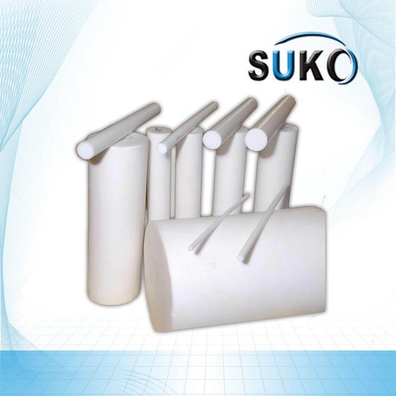
PTFE Rod for Automotive Sealing
The Problem: Why Rubber Seals Fail
Rubber seals are elastomeric — they rely on flexibility to create a sealing interface. But flexibility comes with trade-offs:
-
Heat degradation — Above 150°C, most rubber compounds begin to harden, crack, or lose elasticity
-
Chemical attack — Brake fluid, transmission oil, and fuel additives cause rubber to swell, extract, or degrade
-
Compression set — Rubber permanently deforms under sustained pressure, losing sealing force over time
-
Aging — UV exposure and ozone cause surface cracking and embrittlement
In critical automotive systems — engines, transmissions, brake systems — rubber seals typically require replacement within 5–8 years, and failure often occurs without warning, leading to fluid leaks, component damage, and costly repairs.
PTFE solves all of these problems.
Why PTFE Rod Is Different
PTFE (polytetrafluoroethylene) is not an elastomer. It’s a fluoropolymer with a unique combination of properties that makes it ideal for demanding sealing applications.
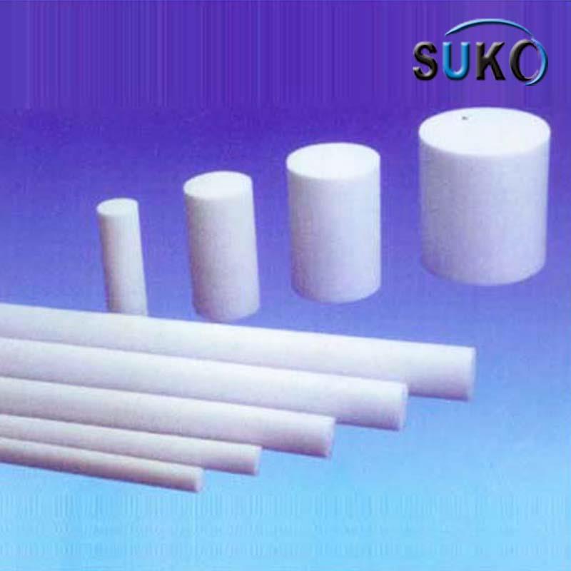
PTFE Rod for Automotive Sealing
1. Ultra-Low Friction
PTFE has one of the lowest coefficients of friction of any solid material — typically ≤0.04. This means PTFE seals generate less heat during operation, reduce wear on mating surfaces, and lower power consumption in rotating applications.
In an engine crankshaft seal, lower friction translates directly to improved fuel efficiency and longer seal life.
2. Extreme Temperature Range
PTFE maintains its mechanical properties from -180°C to +260°C. This is a range no elastomer can match. Engine compartments routinely exceed 150°C; transmission fluids can reach 120°C; brake systems generate high heat during repeated stops. PTFE holds its integrity where rubber fails.
3. Chemical Inertness
PTFE resists virtually all chemicals — including brake fluid, transmission oil, engine coolant, fuel, and additives. It does not swell, soften, or degrade. This is why PTFE is the material of choice for seals in aggressive fluid environments.
4. Self-Lubricating
PTFE’s inherent lubricity means it does not require external lubrication. This is a critical advantage in applications where lubricant films can be disrupted — such as dry-start conditions or systems with marginal oil supply.
5. Aging Resistance
Unlike rubber, PTFE does not age. It is immune to UV degradation, ozone cracking, and thermal cycling fatigue. Components machined from PTFE rod can outlast the vehicle they are installed in.
Where PTFE Rod Is Used in Automotive Sealing
PTFE rod is machined into finished sealing components across eight major automotive systems. The table below shows each system, the specific components, and why PTFE is the preferred material.
| System | Components | Why PTFE? |
|---|---|---|
| Engine | Valve stem seals, crankshaft oil seals, camshaft seals, gaskets | Withstands 200°C+ oil, maintains sealing force under thermal cycling |
| Transmission | Piston seals, sealing rings, guide rings | Resists ATF additives, maintains pressure at high temperatures |
| Brake Systems | Master cylinder seals, caliper seals, ABS seals | Inert to brake fluid, low friction for smooth piston movement |
| Steering Systems | Power steering seals, rack-and-pinion seals | Withstands high pressure, resists PS fluid degradation |
| Suspension | Shock absorber seals, guide rings | Endures continuous reciprocating motion, heavy loads |
| Hydraulic/Pneumatic | Piston rings, rod seals, guide rings | Leak-proof under high pressure, self-lubricating |
| Fuel Systems | Injector seals, fuel pump seals, EVAP seals | Resists fuel and ethanol blends, no swelling |
| Electrical/Sensor | Insulating components, sensor seals, connector seals | Excellent dielectric properties, protects against contamination |
Ram Extrusion vs. Molded Rod: What’s the Difference?
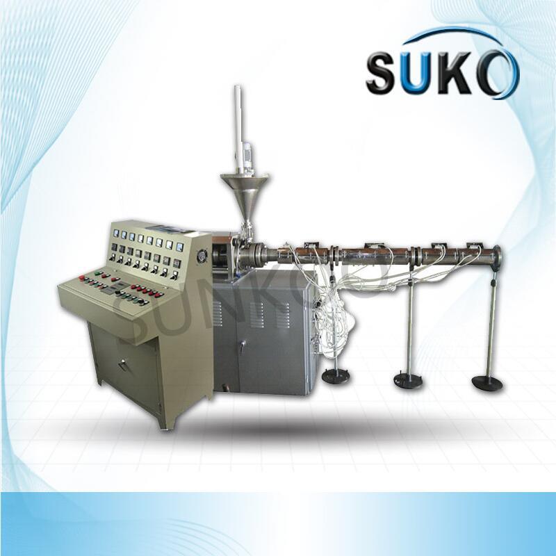
Extruder Automatic Machine polymer PTFE Rod Ram
PTFE rod is manufactured using two primary methods: molding and ram extrusion. The choice matters.
Molded PTFE Rod
-
Produced by compressing PTFE resin in a heated mold
-
Limited to relatively short lengths (typically up to 300mm)
-
Can have inconsistent density due to non-uniform pressure distribution during molding
-
Best for applications requiring large diameters (200mm+) where extrusion is not feasible
Ram Extruded PTFE Rod
-
Produced by feeding PTFE resin into a heated cylinder and forcing it through a die using a hydraulic ram
-
Continuous production — unlimited length
-
Uniform density and consistent material properties
-
Superior machinability and surface finish
-
Consistent diameters across the entire length
For automotive sealing applications, ram extruded PTFE rod is nearly always the preferred choice. Precision-machined seals and piston rings require consistent material throughout the component. Ram extrusion delivers that consistency.
SUKO’s PTFE rod is manufactured exclusively through ram extrusion — providing sealing manufacturers with uniform, machinable rod across the full diameter range.
What Makes SUKO’s PTFE Rod Different
Most PTFE rod suppliers rely on a single extruder, limiting their diameter range and forcing customers to source different sizes from multiple vendors. This creates several problems:
-
Inconsistent quality across different suppliers
-
Higher logistics costs from multiple shipments
-
Varying lead times for different diameters
-
No single point of accountability for quality
SUKO operates multiple PTFE ram extruders across different specifications:
| Diameter Range | Equipment | Process |
|---|---|---|
| 4mm – 20mm | PFLB20 | Vertical Extrusion |
| 25mm – 80mm | PFB80 | Horizontal Extrusion |
| 80mm – 150mm | PFB150 | Horizontal Extrusion |
| 20mm – 500mm | PFMY500 | Vertical Extrusion |
This means SUKO can produce PTFE rod across a continuous diameter range from 4mm to 500mm — all in-house, all on our own equipment.
SUKO designs and builds its own production equipment — a distinction that sets it apart from most PTFE suppliers who rely on off-the-shelf machines. This gives SUKO complete control over every variable: pressure control, temperature profiles, extrusion speed, and final machining.
What this means for sealing manufacturers:
-
One Supplier, Any Diameter — Need 6mm rod for a small seal? 50mm for a piston ring? 300mm for a large guide ring? SUKO covers the full range. No need to source from multiple suppliers.
-
Custom Diameters Available — Standard sizes not fitting your design? SUKO’s in-house extrusion capability means custom diameters are available on request.
-
Consistent Quality, Every Batch — Because SUKO builds its own extruders, the process is controlled from the equipment level — not just inspected after the fact. Batch-to-batch consistency is built in, not checked for.
PTFE Rod Specifications
| Parameter | Specification |
|---|---|
| Material | 100% virgin PTFE (ram extruded) |
| Diameter Range | 4mm – 500mm (custom available) |
| Length | Continuous extrusion — cut to required length |
| Operating Temperature | -180°C to +260°C |
| Friction Coefficient | ≤0.04 |
| Density | 2.10 – 2.30 g/cm³ |
| Tensile Strength | ≥20.0 MPa |
| Elongation at Break | ≥150% |
| Color | Natural white (custom available) |
| Fillers Available | Glass fiber, carbon, graphite, bronze, molybdenum disulfide, stainless steel |
Frequently Asked Questions
Q: What diameter range can SUKO supply for PTFE rod?
A: 4mm to 500mm standard. Custom diameters available on request.
Q: What is the temperature range for PTFE rod?
A: -180°C to +260°C continuous operation.
Q: Can PTFE rod be filled with reinforcing materials?
A: Yes. Glass fiber, carbon, graphite, bronze, molybdenum disulfide, and stainless steel fillers are available.
Q: Do you extrude rod in-house or outsource?
A: In-house. SUKO designs and builds its own ram extruders — full quality control from raw material to finished rod.
Q: Why choose ram extruded PTFE rod over molded rod?
A: Ram extrusion yields superior material homogeneity and density compared to molded rod, making it the preferred choice for precision-machined sealing components.
Q: What automotive applications use PTFE rod?
A: PTFE rod is machined into oil seals, piston rings, guide rings, gaskets, and custom sealing profiles for engines, transmissions, brake systems, steering systems, suspension, hydraulic systems, fuel systems, and electrical systems.
Q: How does PTFE rod compare to rubber seals?
A: Unlike rubber seals that degrade under heat and chemical exposure, PTFE delivers consistent performance where other materials fail — wider temperature range, superior chemical resistance, and self-lubricating properties.
Q: Can SUKO supply custom colors?
A: Yes. Natural white is standard, and custom colors are available for specific applications where color coding is required.
Q: What is the lead time for custom diameter PTFE rod?
A: Lead times vary based on diameter and quantity. Contact our sales team for specific requirements.
Conclusion
PTFE rod has become the material of choice for demanding automotive sealing applications because it outperforms rubber in every measure that matters: temperature range, chemical resistance, friction reduction, and long-term durability. Sealing manufacturers machining PTFE rod into oil seals, piston rings, guide rings, and gaskets benefit from consistent material properties, excellent machinability, and components that outlast the systems they seal.
SUKO’s capability to manufacture PTFE rod across a continuous 4mm to 500mm diameter range — all in-house, all on our own equipment — makes it a single-source supplier for sealing manufacturers who demand consistent quality and the ability to source any size from one reliable partner.
SUKO Polymer Machine Tech Co., Ltd.
-
Email: info@sukoptfe.com
-
Phone/WhatsApp: +86 19975113419
Introduction
The chlor-alkali industry is one of the largest and most demanding sectors in chemical manufacturing. Through the electrolysis of brine, it produces three essential industrial chemicals: chlorine, hydrogen, and caustic soda (sodium hydroxide). The global chlor-alkali market was valued at approximately USD 58–90 billion in 2025 and is projected to grow at a CAGR of 3–5% through the next decade.

Large Diameter PTFE Tube
But here’s the challenge: these products are among the most corrosive substances in industrial processing.
Caustic soda at 32% concentration, hydrochloric acid, and wet chlorine gas are all produced and transported at elevated temperatures — typically 80°C and above. The piping systems that carry these media face a continuous battle against corrosion. And when pipes fail, the consequences are severe: production downtime, safety hazards, environmental violations, and millions in unplanned costs.
This article examines why PTFE (polytetrafluoroethylene) pipe has become the only reliable solution for chlor-alkali caustic soda conveying — and why metal pipes simply cannot compete.
The Problem: Metal Pipes Fail. Repeatedly. Expensively.
In chlor-alkali plants, 32% caustic soda is typically conveyed through DN50–DN500 pipelines from electrolyzers to evaporation and concentration stages. The fluid temperature is approximately 80°C.
For decades, plant engineers have specified 304 stainless steel for these lines. And for decades, they have watched them fail.
The data is alarming:
-
At 80°C in 32% caustic soda service, 304 stainless steel pipes develop pitting corrosion within 6 months
-
Pitting is caused by chloride ions attacking the passive oxide layer on stainless steel surfaces
-
Once pitting begins, it accelerates — leading to through-wall perforation and leakage
-
A chlor-alkali plant in Southeast Asia reported that 304 stainless steel pipes required replacement every 6 months, with each failure causing production stoppages and safety incidents
The cost of metal pipe failure is staggering:
-
Direct costs: Pipe replacement materials and labor
-
Indirect costs: Production downtime, lost output, disposal of contaminated media
-
Hidden costs: Safety inspections, environmental compliance reporting, increased insurance premiums
-
Worst-case costs: Environmental fines, injury claims, reputation damage
One chlor-alkali facility documented that frequent hydrochloric acid pipe replacements cost them over $1 million annually in losses.
What About Other Materials?
Some plants have tried alternatives:
| Material | Problem |
|---|---|
| Carbon steel | Rapid general corrosion in caustic and acid service |
| 304/316 Stainless Steel | Pitting corrosion from chlorides; stress corrosion cracking in caustic |
| Alloy 20 / Hastelloy | Extremely expensive — 5–10× the cost of PTFE solutions |
| Rubber-lined pipe | Degrades at high temperatures; requires frequent relining |
| FRP/GRP | Limited temperature and pressure capability; permeation issues |
The reality: In chlor-alkali service at 80°C with 32% caustic soda, no metallic material offers both corrosion resistance and cost-effectiveness. Exotic alloys like Hastelloy can resist corrosion — but at prices that make them economically unviable for long pipeline runs.
The Solution: PTFE Pipe — 5+ Years, Zero Wall Thickness Change
PTFE (polytetrafluoroethylene) is fundamentally different from metals.
PTFE is a fluoropolymer with exceptional chemical inertness. It is resistant to virtually all industrial chemicals — including concentrated acids, alkalis, and oxidizing agents — except molten alkali metals and elemental fluorine.
The performance comparison is stark:
| Parameter | 304 Stainless Steel | PTFE Pipe |
|---|---|---|
| Service life in 32% caustic at 80°C | 6 months | 5+ years |
| Wall thickness change | Significant | Zero |
| Maintenance frequency | Every 6 months | None |
| Annual maintenance cost | High | 80% reduction |
| Leakage risk | High | Near zero |
| Product contamination risk | Yes (metal ions) | No |
After switching from 304 stainless steel to PTFE pipe, one chlor-alkali plant achieved 5 years of continuous operation without wall thickness change and reduced annual maintenance costs by 80%.
Where PTFE Pipe Is Used in Chlor-Alkali Plants
PTFE pipe serves multiple critical applications across chlor-alkali facilities:
1. 32% Caustic Soda Main Pipelines
The largest-volume application. Electrolyzers produce caustic soda at approximately 80°C, which must be conveyed to evaporation and concentration stages. PTFE pipe handles this service indefinitely.
2. Hydrochloric Acid Conveying
Many chlor-alkali plants produce hydrochloric acid as a co-product. PTFE pipe resists hydrochloric acid at all concentrations and temperatures.
3. Wet Chlorine Gas Transport
Chlorine gas produced by electrolysis is saturated with moisture — forming highly corrosive hydrochloric acid. PTFE pipe is one of the few materials that can handle wet chlorine without degradation.
4. Brine and Salt Slurry Lines
Raw brine and salt slurries contain abrasive particulates and chlorides. PTFE pipe’s low friction surface reduces abrasion and prevents scale buildup.
5. Chemical Waste Disposal
Chlor-alkali plants generate corrosive waste streams. PTFE pipe safely conveys these to treatment facilities.
Why SUKO’s PTFE Pipe Is Different
Most PTFE pipe manufacturers buy off-the-shelf extruders and work within whatever specifications those machines offer. SUKO took a different path.
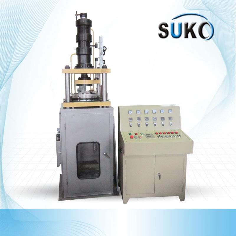
PTFE Tube Ram Extruder Machine PFG500 Dia 300mm-500mm
SUKO designs and builds its own PTFE production equipment — including ram extruders and sintering ovens. This gives complete control over:
-
Extrusion pressure — ensuring uniform density and wall thickness
-
Temperature profiles — optimizing material properties throughout the process
-
Sintering curves — achieving full crystallinity and mechanical strength
-
Final dimensions — holding tight tolerances across every batch
The result: PTFE pipe with consistent quality, batch after batch, in diameters from 5mm to 500mm.
Technical Specifications
| Parameter | Specification |
|---|---|
| Material | 100% virgin PTFE |
| Diameter Range | 5mm – 500mm |
| Operating Temperature | -180°C to +260°C |
| Pressure Rating | Customized by wall thickness |
| Process | Ram extrusion + in-house sintering |
| Fillers Available | Glass fiber, carbon, graphite, bronze, MoS₂ |
Frequently Asked Questions
Q: How long does PTFE pipe last in 32% caustic soda service?
A: At 80°C, PTFE pipe shows no wall thickness change after 5+ years of continuous service — compared to 304 stainless steel which pits within 6 months.
Q: What is the maximum operating temperature for PTFE pipe?
A: PTFE maintains its mechanical properties up to +260°C continuously, and as low as -180°C.
Q: Can PTFE pipe handle wet chlorine?
A: Yes. PTFE is one of the few materials that resists wet chlorine gas without degradation.
Q: What chemicals attack PTFE?
A: Only molten alkali metals, elemental fluorine, chlorine trifluoride, and a few other highly reactive species at elevated temperatures.
Q: What diameter range can SUKO supply?
A: 5mm to 500mm standard. Custom diameters available on request.
Q: Do you outsource extrusion or sintering?
A: No. SUKO operates in-house ram extruders and sintering ovens — full quality control from raw material to finished pipe.
Q: Can PTFE pipe be reinforced with fillers?
A: Yes — glass fiber, carbon, graphite, bronze, and molybdenum disulfide fillers are available for enhanced mechanical properties, thermal conductivity, or wear resistance.
Conclusion
The chlor-alkali industry faces a fundamental challenge: conveying highly corrosive media at elevated temperatures without risking equipment failure, production downtime, or safety incidents. Metal pipes — whether carbon steel, stainless steel, or exotic alloys — either corrode rapidly or are economically unviable.
PTFE pipe offers the only practical solution. With 5+ years of service life in 32% caustic soda at 80°C, zero wall thickness change, and 80% reduction in maintenance costs, PTFE has proven itself as the material of choice for chlor-alkali piping.
SUKO’s in-house manufacturing capability — from ram extrusion to sintering — ensures consistent quality across diameters from 5mm to 500mm. When metal pipes fail and production stops, PTFE pipe keeps the process running.
SUKO Polymer Machine Tech Co., Ltd.
-
Email: info@sukoptfe.com
-
Phone/WhatsApp: +86 19975113419
Introduction
Industrial filtration is the backbone of countless manufacturing processes — from chemical production and pharmaceutical manufacturing to semiconductor fabrication and environmental treatment. The filter media used in these applications must withstand aggressive chemicals, extreme temperatures, and continuous operation without failure.

ePTFE Tube for Industrial Filtration
For decades, conventional plastic filter tubes made from polypropylene (PP), polyethylene (PE), and polyvinyl chloride (PVC) have been the default choice. They are inexpensive, widely available, and adequate for mild service conditions.
But in demanding industrial environments — strong acids, concentrated alkalis, high temperatures, chlorine-containing streams — these materials fail. Rapidly. Expensively. And often without warning.
ePTFE (expanded polytetrafluoroethylene) tube offers a fundamentally different solution. This article explains why ePTFE outperforms conventional plastics in industrial filtration — and why it delivers 5–10× longer service life with zero degradation.
The Problem: Why PP, PE, and PVC Filter Tubes Fail
Conventional plastic filter tubes have inherent limitations that become critical failure points in demanding industrial filtration applications.
Chemical Attack
PP, PE, and PVC are hydrocarbons. They are susceptible to attack from:
-
Strong acids — Sulfuric acid, hydrochloric acid, nitric acid cause swelling, cracking, and embrittlement
-
Strong alkalis — Sodium hydroxide degrades PVC and attacks PP/PE over time
-
Oxidizers — Chlorine, ozone, and hypochlorite break down polymer chains
-
Organic solvents — Many solvents swell or dissolve these materials
In concentrated acid service at elevated temperatures, PP/PE/PVC tubes typically fail within 3–6 months. Failure modes include swelling (loss of dimensional stability), cracking (loss of structural integrity), and complete breakdown (loss of filtration function).
Temperature Limits
Conventional plastics have narrow temperature ranges:
| Material | Maximum Continuous Temperature | Minimum Temperature |
|---|---|---|
| PP | 80°C | 0°C |
| PE | 60°C | -20°C |
| PVC | 60°C | -10°C |
| ePTFE | 260°C | -200°C |
Above these temperatures, PP/PE/PVC soften, deform, and lose mechanical strength. Below these temperatures, they become brittle and crack under stress.
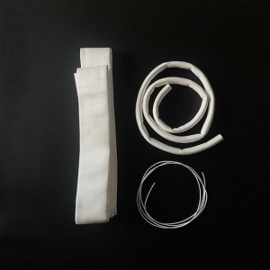
ePTFE Tube for Industrial Filtration
Extractables and Contamination
PP, PE, and PVC contain plasticizers, stabilizers, and other additives that can leach into the product stream. In pharmaceutical, semiconductor, and food applications, this contamination is unacceptable.
The Cost of Failure
When a filter tube fails in an industrial process:
-
Production stops — Downtime costs can exceed thousands of dollars per hour
-
Product is lost — Contaminated batches must be discarded
-
Equipment is damaged — Downstream equipment can be affected
-
Safety is compromised — Leaks of hazardous chemicals create safety risks
-
Regulatory compliance is at risk — Environmental and quality violations
One chemical plant documented that replacing failed PP filter tubes in sulfuric acid service cost them over $200,000 annually in materials, labor, and lost production.
The Solution: ePTFE Tube — 5–10× Longer Life with Zero Degradation
ePTFE is fundamentally different from PP, PE, and PVC. It is a fluoropolymer with a unique combination of properties that make it ideal for demanding filtration applications.
Exceptional Chemical Resistance
PTFE is chemically inert to virtually all industrial chemicals except molten alkali metals and elemental fluorine. This includes:
-
All acids — Sulfuric, hydrochloric, nitric, hydrofluoric, phosphoric
-
All alkalis — Sodium hydroxide, potassium hydroxide
-
All oxidizers — Chlorine, ozone, sodium hypochlorite, hydrogen peroxide
-
All solvents — Organic and inorganic solvents
This means ePTFE tubes do not swell, crack, degrade, or leach — regardless of the chemical environment.
Extreme Temperature Range
ePTFE maintains its mechanical properties from -200°C to +260°C. This enables filtration applications that are impossible with conventional plastics:
-
Hot acid filtration — Concentrated acids at 80–150°C
-
Hot alkaline streams — Caustic solutions at elevated temperatures
-
Flue gas filtration — Baghouse systems operating at 200°C+
-
Cryogenic filtration — Low-temperature gas and liquid processing
High Porosity, Low Pressure Drop
The biaxial stretching process used to manufacture ePTFE tubes creates a microporous structure with:
-
Porosity of 50%–85% — This means less material to block flow
-
Billions of uniform pores per square centimeter — Consistent filtration throughout
-
High flux rates — More throughput with less energy
In comparison, PP/PE/PVC tubes have lower porosity and higher pressure drop, meaning they require more energy to achieve the same flow rate.
No Extractables, No Contamination
ePTFE contains no plasticizers, stabilizers, or additives that can leach into the product stream. This makes it ideal for:
-
Pharmaceutical filtration — No contamination of drug products
-
Semiconductor processing — No trace contaminants affecting chip yields
-
Food and beverage — FDA-compliant, no extractables
Fouling Resistance and Cleanability
ePTFE’s low surface energy (approximately 18–24 mN/m) means:
-
Foulants do not adhere strongly — Less fouling during operation
-
Backwashing is highly effective — Flux recovery >90% after cleaning
-
Extended service life — Less frequent cleaning and replacement
Performance Comparison: ePTFE vs. PP/PE/PVC
| Property | PP/PE/PVC | ePTFE | Advantage |
|---|---|---|---|
| Chemical resistance | Limited | pH 0–14, all chemicals | ePTFE |
| Max temperature | 60–80°C | 260°C | ePTFE |
| Min temperature | -20 to 0°C | -200°C | ePTFE |
| Porosity | 40–60% | 50–85% | ePTFE |
| Extractables | Yes | None | ePTFE |
| Service life | 3–12 months | 5–10× longer | ePTFE |
| Flux recovery | 60–80% | >90% | ePTFE |
| Cost | Lower upfront | Higher upfront | PP/PE/PVC |
The ROI of ePTFE
While the upfront cost of ePTFE tubes is higher than PP/PE/PVC, the total cost of ownership is often lower due to:
-
5–10× longer service life — Fewer replacements
-
Reduced downtime — Less frequent change-outs
-
Lower energy consumption — Higher porosity means less pressure drop
-
Better product quality — No contamination from extractables
-
Less maintenance labor — Fewer interventions
Applications Requiring ePTFE
ePTFE tubes are essential in applications where conventional plastics cannot survive:
Chemical Processing
-
Concentrated sulfuric acid filtration
-
Hydrochloric acid service
-
Nitric acid processing
-
Sodium hydroxide streams
-
Aggressive organic solvents
Pharmaceutical and Biotechnology
-
Sterile filtration of solvents
-
Fermentation air filtration
-
Drug product filtration
-
Steam-sterilizable applications
Semiconductor Manufacturing
-
Ultra-pure water filtration
-
High-purity chemical filtration (etching, cleaning, photolithography)
-
Contamination-sensitive processes
Industrial Wastewater Treatment
-
PCB acid wash solutions
-
Electroplating waste liquids
-
Steel pickling acids
-
Landfill leachate treatment
High-Temperature Flue Gas
-
Waste incineration
-
Coal-fired power plants
-
Cement kilns
-
Metallurgical furnaces
-
Pulse-jet cleaning systems
Why SUKO’s ePTFE Tube Is Different
SUKO manufactures ePTFE tube from 100% virgin PTFE resin through a precision biaxial stretching process, ensuring:
-
Uniform pore size distribution — Consistent filtration performance throughout the tube
-
Batch-to-batch consistency — Every batch performs identically
-
Customizable pore sizes — From 0.05μm to 10μm
-
Custom dimensions — Diameters, wall thicknesses, and lengths to your specifications
SUKO has 14 years of experience in PTFE R&D and manufacturing, with products exported to more than 40 countries. Every batch undergoes rigorous performance testing to guarantee stable filtration precision and flow rate.

Custom PTFE Parts Manufacturer – Engineered by Suko Machinery | Suko
Frequently Asked Questions
Q: What chemicals does ePTFE resist?
A: pH 0–14, including strong acids, strong alkalis, oxidizers, and organic solvents. Only molten alkali metals and elemental fluorine attack PTFE.
Q: What is the temperature range for ePTFE tube?
A: -200°C to +260°C continuous operation.
Q: How long does ePTFE tube last compared to PP/PE/PVC?
A: 5–10× longer under the same service conditions.
Q: What pore sizes are available?
A: Customizable from 0.05μm to 10μm.
Q: Does ePTFE tube contain extractables?
A: No. ePTFE contains no plasticizers, stabilizers, or additives that can leach into the product stream.
Q: Can ePTFE tube be backwashed?
A: Yes. Flux recovery exceeds 90% after backwashing.
Q: What applications require ePTFE?
A: Chemical processing, pharmaceutical manufacturing, semiconductor fabrication, industrial wastewater treatment, and high-temperature flue gas filtration.
Q: Can pore size, diameter, and length be customized?
A: Yes. Custom pore sizes from 0.05μm to 10μm. Custom diameters, wall thicknesses, and lengths available upon request.
Conclusion
PP, PE, and PVC filter tubes have their place in mild service conditions. But in demanding industrial environments — strong acids, concentrated alkalis, high temperatures, and oxidizer-containing streams — they fail rapidly and expensively.
ePTFE tube offers a fundamentally better solution: 5–10× longer service life, zero degradation, no contamination, and stable performance across -200°C to +260°C and pH 0–14. While the upfront cost is higher, the total cost of ownership is often lower — and in many applications, ePTFE is the only material that can survive at all.
SUKO’s ePTFE tube is manufactured in-house with precision control over pore size, dimensions, and quality consistency — delivering reliable filtration performance across the most demanding industrial applications.
SUKO Polymer Machine Tech Co., Ltd.
-
Email: info@sukoptfe.com
-
Phone/WhatsApp: +86 19975113419
Introduction
Guide rails are the backbone of countless industrial machines — injection molding machines, stamping presses, food packaging equipment, machine tools, and more. They guide heavy components through millions of precisely controlled movements, day after day, year after year.
But guide rails face a persistent challenge: friction.
Metal rails sliding against metal components generate heat, consume energy, and wear down over time. Lubrication helps — but in many environments, oil and grease are either impractical or completely prohibited. Food processing plants cannot risk oil contamination. Cleanrooms cannot tolerate airborne lubricant particles. Ovens bake lubricants into carbon deposits. And in every case, metal-on-metal contact eventually leads to wear, stick-slip, and costly downtime.
PTFE sheet, bonded to guide rail surfaces as a wear-resistant liner, solves all of these problems. This article explains why PTFE sheet has become the go-to solution for industrial guide rail lining — and why it delivers longer equipment life, lower maintenance costs, and more consistent production quality.
The Problem: Why Traditional Guide Rails Fail
Metal-on-Metal Wear
In a conventional guide rail system, metal slides against metal. Despite lubrication, the sliding surfaces experience continuous abrasion. Over time, the rail surface wears unevenly, creating grooves, high spots, and dimensional inaccuracies. The moving component no longer tracks straight — leading to misalignment, increased friction, and eventual component failure.
The cost of rail wear is significant:
-
Loss of precision — Parts no longer meet specifications
-
Increased scrap rates — Rework and waste
-
Downtime — Unscheduled repairs and adjustments
-
Replacement costs — Rail resurfacing or replacement is expensive
The Lubrication Problem
In many industrial environments, conventional lubrication is not an option:
| Environment | Why Oil Fails |
|---|---|
| Food Processing | Oil contaminates products — health and safety risk |
| Cleanrooms | Oil particles compromise cleanliness |
| Ovens/High Heat | Oil bakes into carbon deposits, becomes abrasive |
| Underwater | Oil disperses, washes away, or contaminates water |
| Vacuum | Oil outgasses, contaminates the vacuum environment |
| Dusty Environments | Oil attracts dust, creates grinding paste |
Stick-Slip: The Precision Killer
When a heavy slide is driven by a hydraulic or mechanical actuator, the static friction (the force required to start movement) is higher than the dynamic friction (the force required to keep it moving). This difference causes a phenomenon called stick-slip: the slide hesitates, jumps forward, hesitates again — creating jerky, uncontrolled motion that ruins precision.
Stick-slip is most severe at low speeds. In machine tools, it appears as chatter marks on the workpiece. In injection molding machines, it causes inconsistent clamping pressure. In food packaging equipment, it leads to inconsistent seals.
The Solution: PTFE Sheet Guide Rail Lining
How PTFE Sheet Works
PTFE sheet is bonded to the metal guide rail surface. The moving component — whether a slide, a clamping unit, or a carriage — rides on the PTFE surface rather than directly on the metal rail.
This changes the friction pair from metal-on-metal to PTFE-on-metal.

PTFE Sheet for Guide Rail Lining
PTFE (polytetrafluoroethylene) is a fluoropolymer with unique properties that make it ideal for guide rail lining:
Ultra-Low Friction
PTFE has one of the lowest coefficients of friction of any solid material — typically ≤0.04. For comparison:
| Material Pair | Coefficient of Friction |
|---|---|
| Steel on steel (lubricated) | 0.05–0.10 |
| Steel on steel (dry) | 0.15–0.30 |
| PTFE on steel (dry) | 0.04–0.08 |
PTFE requires no lubrication. It is self-lubricating, meaning it slides smoothly even in dry-running conditions.
Static and Dynamic Friction Nearly Equal
Unlike most materials, PTFE has nearly identical static and dynamic friction coefficients. This means:
-
No static friction “spike” to overcome
-
No stick-slip
-
Smooth startup and precise positioning
-
Better surface finish on machined parts
Extreme Temperature Range
PTFE sheet performs reliably from -180°C to +260°C. This makes it suitable for:
-
Cryogenic applications
-
High-temperature ovens and dryers
-
Steam-sterilized equipment
-
Outdoor equipment exposed to extreme weather
Corrosion Resistance
PTFE is chemically inert. It resists cutting fluids, mild acids, steam, alkalis, and most chemicals. In corrosive environments where metal guide rails would rust or pit, PTFE-lined rails continue to perform.
Wear Protection (Sacrificial Layer)
The PTFE sheet acts as a sacrificial layer. Wear occurs on the PTFE sheet — not on the expensive metal rail. When the sheet eventually wears down, it is peeled off and replaced with a new strip. The metal rail underneath remains pristine.
This transforms a major rail overhaul — which requires disassembly, resurfacing, and days of downtime — into a simple, in-place maintenance task that takes minutes.
Performance Comparison
| Property | Metal-on-Metal (Lubricated) | Metal-on-Metal (Dry) | PTFE Sheet on Metal |
|---|---|---|---|
| Friction coefficient | 0.05–0.10 | 0.15–0.30 | 0.04–0.08 |
| Stick-slip | Present | Severe | Eliminated |
| Lubrication required | Yes | Yes | No |
| Rail wear | Moderate | Severe | None (sacrificial layer) |
| Replacement time | Days (rail resurfacing) | Days | Minutes (replace tape) |
| Temperature range | -20°C to 120°C | -20°C to 120°C | -180°C to +260°C |
| Chemical resistance | Limited | Limited | Excellent |
Industry Applications
Injection Molding Machines
Injection molding machine clamping units cycle tens of thousands of times daily. The guide rails must maintain precise alignment under heavy loads. Oil contamination on the mold surface scraps entire production batches — making PTFE’s dry-running capability essential. PTFE sheet lining eliminates oil-related risks, prevents rail wear, and maintains clamping precision across millions of cycles.
Food Packaging Equipment
Food packaging sealing mechanism guide rails cannot use lubricants. Oil mist or drips contaminate packaging materials and trigger product recalls. PTFE sheet is FDA-compliant, runs dry, maintains an ultra-low friction coefficient, and performs reliably even inside 260°C oven environments.
Machine Tools (Mills, Lathes)
At low feed rates, stick-slip is the primary cause of poor surface finish. Metal guide rails have a static friction coefficient higher than dynamic friction — the slide hesitates, jumps, hesitates again, leaving chatter marks on every workpiece. PTFE sheet has static and dynamic friction coefficients that are nearly identical, eliminating stick-slip entirely. The slide moves smoothly and precisely at any feed rate.
Why SUKO’s PTFE Sheet Is Different
Most PTFE parts manufacturers buy off-the-shelf machines and work within whatever precision those machines offer. SUKO took a different path: we design and build our own production equipment — including high-precision automatic molding machines, ram extruders, and sintering furnaces.
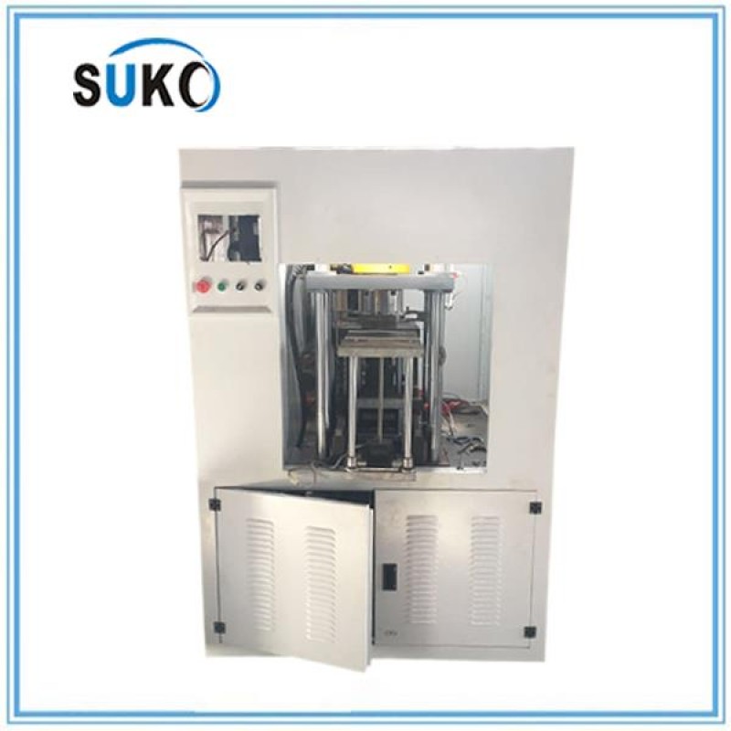
Automatic PTFE Hydraulic Press Moulding Machine
From pressure control and temperature profiles to final machining, we control every variable. When we want tighter tolerances, we tune our machines to deliver them. Not by inspection, but at the equipment level. That’s how we hold this PTFE sheet to ±0.05mm thickness tolerance, batch after batch.
Case in Point
Our Thailand-based customer Thiti regularly orders this PTFE sheet in 50mm × 5mm × 1.2m size — the industry’s most standard size for guide rail lining. He chose SUKO because local suppliers couldn’t hold consistent thickness — shipments varied batch to batch, causing rework during installation. We hold it to ±0.05mm, every batch. That’s because we build our own machines and tune them to that precision — not just measure it after the fact.
Frequently Asked Questions
Q: Does PTFE sheet require lubrication?
A: No. PTFE is self-lubricating. It requires no oil or grease.
Q: What is the coefficient of friction?
A: ≤0.04 — among the lowest of any solid material.
Q: Does PTFE sheet eliminate stick-slip?
A: Yes. Static and dynamic friction coefficients are nearly identical, eliminating stick-slip entirely.
Q: What is the temperature range?
A: -180°C to +260°C continuous operation.
Q: How long does PTFE sheet last?
A: Service life varies by application. In typical guide rail service, 2–5 years before requiring replacement.
Q: What thickness tolerance does SUKO hold?
A: ±0.05mm, batch after batch.
Q: Can sizes be customized?
A: Yes — custom widths, thicknesses, lengths, and cut-outs available.
Q: What industries use PTFE sheet for guide rail lining?
A: Injection molding, stamping/pressing, food packaging, machine tools, elevators, woodworking, paper manufacturing, and more.
Conclusion
Guide rail wear and stick-slip are persistent problems in industrial machinery — problems that lead to precision loss, increased scrap rates, downtime, and costly repairs. Traditional solutions rely on lubrication and metal-on-metal contact, both of which have fundamental limitations.
PTFE sheet guide rail lining offers a fundamentally better solution:
-
No lubrication — Suitable for food plants, cleanrooms, ovens, underwater, and vacuum
-
No stick-slip — Smooth startup and precise positioning
-
Protects metal rails — Sacrificial layer takes the wear, rail stays new
-
Minute-long replacement — Not days-long overhaul
-
Wide temperature range — -180°C to +260°C
SUKO’s PTFE sheet is manufactured in-house with ±0.05mm thickness tolerance — delivering consistent performance, batch after batch.
SUKO Polymer Machine Tech Co., Ltd.
-
Email: info@sukoptfe.com
-
Phone/WhatsApp: +86 19975113419
The Arab Water Crisis: A Matter of Survival
Water scarcity is not an abstract environmental concern for the Arab region — it is a matter of daily survival. The Arabian Peninsula is one of the driest regions on Earth, with natural freshwater resources so limited that GCC countries now depend heavily on desalination for their water supply. Decades of rapid population growth, urbanization, and industrial development have pushed demand far beyond what groundwater and rainfall can sustain.
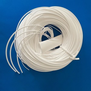
ePTFE Hollow Fiber Membrane and Tube
The scale of the challenge is staggering. The Middle East and Africa region dominates the global desalination market, holding a 52.95% market share in 2024. GCC nations collectively represent over 45 percent of global desalination capacity, with more than 8,950 desalination plants operating in the region. Saudi Arabia alone contributes approximately 20 percent of global capacity.
Saudi Arabia’s desalination capacity is set to increase from 5.6 million cubic meters per day in 2022 to 8.5 million in 2025, and it will have to cover more than 90% of the country’s water consumption. The same holds for the UAE. By 2050, freshwater production by desalination plants is projected to increase more than sixfold compared to today’s levels.
Why Traditional Desalination Has Limits — And Why Arab Nations Are Looking for Better Solutions
The Arab region has relied heavily on thermal desalination technologies — Multi-Stage Flash (MSF) and Multi-Effect Distillation (MED) — for decades. These processes are energy-intensive and capital-intensive, consuming vast amounts of fossil fuels. In an era of decarbonization and rising energy costs, this model is increasingly unsustainable.
Reverse Osmosis (RO) has gained ground as a more energy-efficient alternative. The UAE’s Taweelah desalination plant, the world’s largest RO facility, produces approximately 900,000 tons of freshwater daily near Abu Dhabi. Dubai’s Hassyan complex, another mega-RO project, is expected to reach full completion in Q1 2027.
But RO has its own limitations — high-pressure operation, membrane fouling, and most critically, the challenge of brine disposal. The Arabian Gulf, where most Gulf desalination plants operate, has historically high salinity levels, and brine discharge from hundreds of plants significantly affects local marine ecosystems. The region faces a pressing need for technologies that can concentrate brine further — reducing environmental impact while recovering more water and valuable minerals.
Membrane Distillation: The Next Generation for the Gulf
Membrane Distillation (MD) is emerging as a promising solution, particularly for the challenging conditions of the Arabian Gulf. MD is a thermal-driven process that uses a hydrophobic microporous membrane to separate water vapor from liquid feed. Unlike RO, MD operates at near-atmospheric pressure, reducing energy costs, and can utilize low-grade waste heat — a resource abundant in the Gulf’s industrial sector.
MD also delivers salt rejection rates of ≥99.9%, making it ideal for treating high-salinity feed water and concentrating RO brine. For Gulf nations committed to Zero Liquid Discharge (ZLD) — a goal increasingly embedded in Saudi Vision 2030 and UAE sustainability strategies — MD represents a critical enabling technology.

ePTFE Hollow Fiber Membrane and Tube
Why ePTFE Hollow Fiber Is the Only Viable Membrane for Gulf MD
The success of MD depends entirely on the membrane. The feed water in the Arabian Gulf is highly saline, warm, and biologically active. Membranes must resist fouling, chemical attack, and thermal degradation.
PVDF and PP hollow fiber membranes — the conventional choices — fail under these conditions. They degrade under chlorine exposure, soften at elevated temperatures, lose hydrophobicity, and suffer from low tensile strength.
ePTFE (expanded polytetrafluoroethylene) is fundamentally different.
-
Superior chemical resistance — pH 0–14 tolerance. Resists chlorine, ozone, sodium hypochlorite — the cleaning agents used in every desalination plant. No swelling, no degradation.
-
Extreme temperature range — Continuous operation from -190°C to +280°C. Gulf seawater is warm; MD operates at 60–80°C; ePTFE handles it easily.
-
Strong hydrophobicity — Contact angle ≥128° (up to 152° with treatment). Prevents membrane wetting — the most common and catastrophic failure mode in MD.
-
High salt rejection — ≥99.9% in vacuum membrane distillation (VMD) mode.
-
High tensile strength — Resists breakage during operation, backwashing, and handling.
-
Customizable pore structure — Pore size from 0.05μm to 1.0μm, optimized for specific applications.
Research has demonstrated the effectiveness of PTFE hollow fiber membranes for treating high-salinity Persian Gulf seawater using solar-assisted air gap membrane distillation. Studies on vacuum membrane distillation (VMD) with PTFE hollow fiber membranes have shown strong performance in concentrating brine from RO desalination plants. Multiple-effect membrane distillation (MEMD) using PTFE hollow fiber membranes has been developed for deep concentration of high-salinity solutions.
SUKO’s 14 Years of ePTFE Expertise — Serving the Arab Region
SUKO has been developing ePTFE technology since 2012 — 14 years of continuous research and manufacturing. Our ePTFE hollow fiber membranes and tubes have been deployed across multiple demanding industrial sectors, including seawater desalination, chemical wastewater treatment, pharmaceutical filtration, semiconductor ultrapure water, and high-temperature flue gas treatment.
We understand the specific challenges of the Gulf environment — the high salinity, the warm feed water, the aggressive cleaning protocols required to control biofouling. Our ePTFE hollow fiber products are engineered to withstand these conditions, delivering 3–5+ years of service life — significantly longer than PP or PVDF alternatives.
Specifications
| Parameter | Specification |
|---|---|
| Material | 100% virgin ePTFE |
| Fiber/Tube ID | 0.5 – 3.0mm |
| Fiber/Tube OD | 1.3 – 4.0mm |
| Wall Thickness | 0.1 – 0.8mm |
| Pore Size | 0.05 – 1.0μm (customizable) |
| Operating Temperature | -190°C to +280°C |
| Chemical Resistance | pH 0–14 |
| Contact Angle | ≥128° (up to 152°) |
| Salt Rejection | ≥99.9% |
Conclusion
The Arab region’s water security depends on desalination — and the next generation of desalination depends on membrane technology that can handle the Gulf’s challenging conditions.
ePTFE hollow fiber membrane and tube deliver:
-
≥99.9% salt rejection — consistently high-quality water
-
-190°C to +280°C — handles Gulf temperatures with ease
-
pH 0–14 chemical resistance — withstands aggressive cleaning
-
Contact angle ≥128° — prevents wetting, ensures stable operation
-
3–5+ year service life — lower total cost of ownership
-
Customizable — pore size, dimensions tailored to your application
SUKO has 14 years of ePTFE experience across desalination, chemical, pharmaceutical, semiconductor, and industrial filtration applications. We understand not just how to make ePTFE hollow fiber products, but how they perform in the real world — and we’re ready to support the Arab region’s water security goals.
SUKO Polymer Machine Tech Co., Ltd.
-
Email: info@sukoptfe.com
-
Phone/WhatsApp: +86 19975113419
Unmatched Temperature Range: -196°C to +700°C
Most base station liquid cooling hoses on the market are rated for -40°C to +150°C — barely meeting the outdoor demands of 5G AAU installations. SUKO’s PTFE corrugated tube operates from -196°C to +700°C. That’s a 500°C+ safety margin at the high end and a 150°C+ margin at the low end.

PTFE Corrugated Tube for Base Station Liquid Cooling
Why this matters for 5G base stations:
| Requirement | Typical Hose | SUKO PTFE Corrugated Tube |
|---|---|---|
| Outdoor AAU temperature range | -40°C to +85°C | -196°C to +700°C |
| Safety margin | Minimal | Extreme |
| Thermal cycling aging | Rubber hardens/cracks | No degradation |
| High-temp coolant handling | Softens above 100°C | Stable to 700°C |
| Service life | 3–5 years | 10+ years |
Product Overview
PTFE corrugated tube is a flexible pipeline component manufactured from polytetrafluoroethylene through continuous extrusion on specialized corrugating machines. Its corrugated wall structure provides excellent bending performance and fatigue resistance, while retaining PTFE’s inherent chemical inertness and ultra-wide temperature stability.
Key Features:
| Feature | Specification |
|---|---|
| Operating Temperature | -196°C to +700°C |
| Max Working Pressure | Up to 10MPa |
| Diameter Range | DN1/2 – 32 inch |
| Tube Material | SS304, SS316L |
| Wall Thickness | 0.18 – 2.0mm |
| Braided Mesh | SS304, single or double layer |
| Connection Types | Flange, thread, welded |
| Standards | ANSI, JIS, DIN, GOST |
Core Advantages:
-
Effectively absorbs vibration, noise, and thermal expansion from pipeline systems
-
Compensates for minor deviations in pipe connections and eliminates residual stress
-
Suitable for repeated motion in high-temperature areas with excellent anti-fatigue performance
-
Good flexibility, high-temperature resistance, and corrosion resistance
-
Outstanding coefficient of friction — among the lowest known
-
Excellent acid and chemical resistance
-
Water repellent and electrically resistant
Why Base Station Liquid Cooling Needs PTFE Corrugated Tube
5G base station liquid cooling systems have four critical requirements that make PTFE corrugated tube the superior choice:
1. Extreme Outdoor Temperature Variations
AAU (Active Antenna Unit) is installed on outdoor towers, exposed to severe temperature swings from -40°C to +85°C. PTFE corrugated tube operates from -196°C to +700°C — far exceeding real-world requirements with a massive safety margin. Rubber hoses harden and crack in extreme cold; PTFE remains flexible. Rubber hoses soften and degrade in high heat; PTFE remains stable.
2. Long-Term Maintenance-Free Operation
Base stations are widely distributed with high maintenance costs, requiring pipeline service life of 10+ years. PTFE material is aging-resistant, weather-resistant, and does not become brittle — significantly outlasting rubber hoses under identical operating conditions.
3. Vibration and Thermal Expansion Absorption
Fans, compressors, and other equipment inside AAU generate continuous vibration. PTFE corrugated tube effectively absorbs vibration, noise, and thermal expansion while compensating for minor connection deviations and eliminating residual stress.
4. Coolant Compatibility
Base station liquid cooling commonly uses ethylene glycol, propylene glycol, fluorinated fluids, and deionized water. PTFE offers excellent acid and chemical resistance — no swelling, no leaching, no degradation.
Customization Options
SUKO offers multiple PTFE corrugated tube customization options for different base station liquid cooling scenarios:
| Customization Type | Features | Applications |
|---|---|---|
| Inner-Smooth Outer-Corrugated | Smooth inner wall, corrugated outer; minimal flow resistance | High-flow cooling circuits |
| Smooth Inner Wall | Extremely low friction surface | High-velocity coolant transfer |
| Double-End Recessed | Compressed ends for easy fitting installation | Quick-connect systems |
Custom diameters, wall thicknesses, lengths, and corrugation profiles available.
What Makes SUKO Different
We build the machines that make the tube.
SUKO designs and manufactures its own PTFE corrugated pipe machines, giving us complete control over product quality from the equipment level:
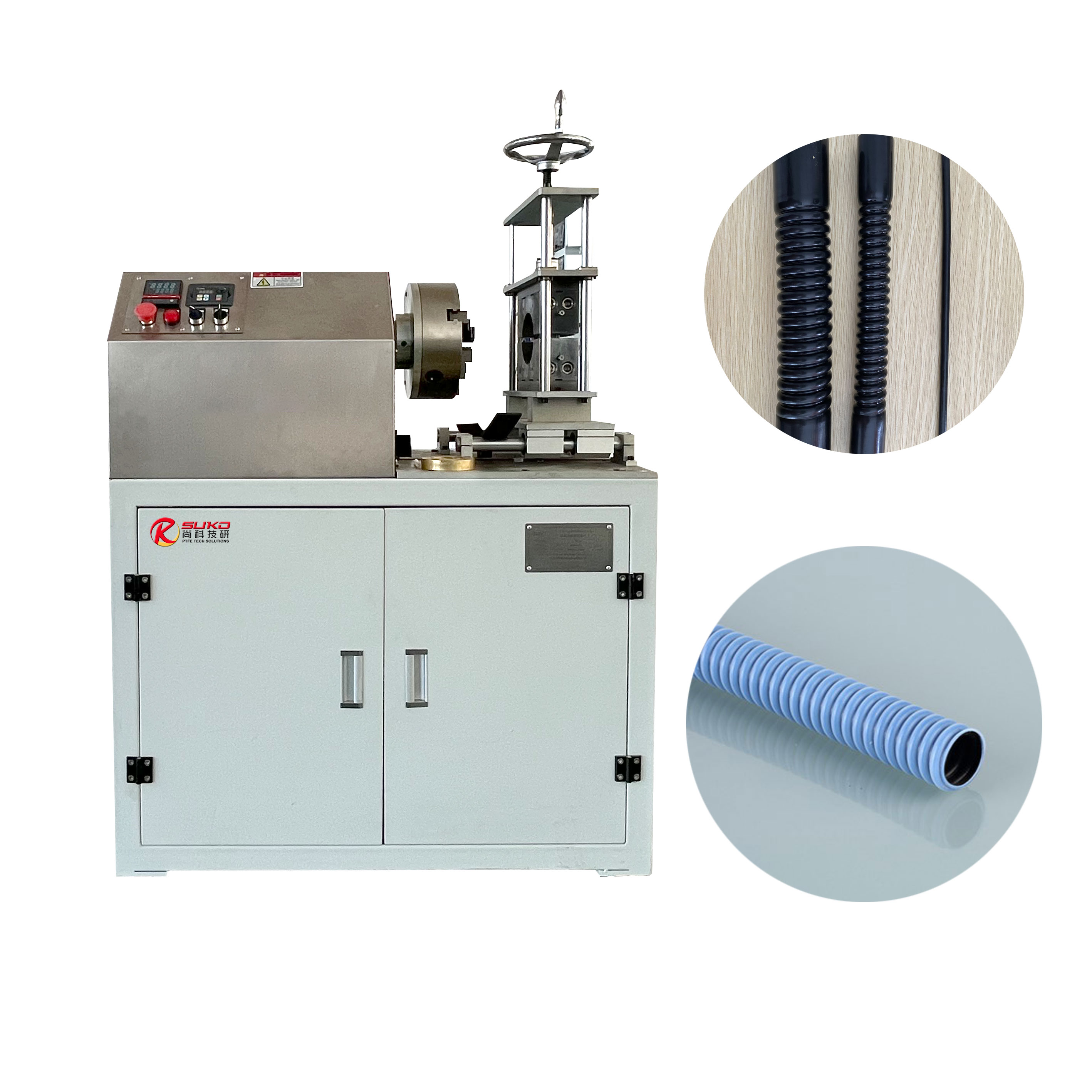
PTFE Plastic Corrugated Pipe Machine
Machine Models:
| Model | Diameter Range | Wall Thickness | Output |
|---|---|---|---|
| SK-50 | 0.8–50mm | 0.5–2mm | 12–30m/h |
| SK-70 | 50–70mm | 0.5–2mm | 12–30m/h |
| SK-100 | 70–100mm | 0.5–2mm | 12–30m/h |
Benefits:
-
Consistent corrugation geometry and uniform wall thickness
-
Custom diameters, wall thicknesses, and corrugation profiles available
-
Full quality control — built in at the equipment level, not just inspected after production
-
Complete specification coverage from DN1/2 to 32-inch
Customer Cases
-
Turkey — ŞEVVAL ATASEL — PTFE corrugated tubes for telecommunications and industrial pipeline projects
-
India — polyhose — PTFE corrugated tubes for automotive and hydraulic applications
Numerous global customers have also purchased SUKO’s PTFE corrugated pipe machines for in-house production across chemical, pharmaceutical, automotive, and electrical industries.
Specifications
| Parameter | Specification |
|---|---|
| Nominal Diameter | DN1/2 – 32 inch |
| Tube Material | SS304, SS316L |
| Wall Thickness | 0.18 – 2.0mm |
| Braided Mesh | SS304, single or double layer |
| Max Working Pressure | 10MPa |
| Operating Temperature | -196°C to +700°C |
| Connection Type | Flange, thread, welded |
| Standards | ANSI, JIS, DIN, GOST |
| Flange Material | Stainless steel or carbon steel |
| Assembly Length | Customized per client requirements |
FAQ
Q: What is the operating temperature range?
A: -196°C to +700°C — far exceeding any base station outdoor requirement.
Q: How does this compare to standard hoses?
A: Most base station cooling hoses are rated -40°C to +150°C. SUKO’s PTFE corrugated tube provides a 500°C+ advantage at the high end.
Q: Can you customize diameter and length?
A: Yes. Custom diameters, wall thicknesses, and lengths are available.
Q: What connection types are supported?
A: Flange, thread, and welded connections.
Q: What is the maximum working pressure?
A: Up to 10MPa.
Q: Do you manufacture the corrugating machines?
A: Yes. SUKO designs and builds its own PTFE corrugated pipe machines — giving us full control over quality and customization.
SUKO Polymer Machine Tech Co., Ltd.
-
Website: https://www.sukopolymer.com/
-
Email: info@sukoptfe.com
-
Phone/WhatsApp: +86 19975113419
Custom PTFE Parts? Ask the Manufacturer Who Builds the Machines.
Submit your design requirements and get a quote directly from the source - factory price, full control, quick response.
 English
  Russian
  Portuguese
  Arabic